

- Originally published September 25, 2018.
I made a tool called a mortise depth gauge. I documented the process using my better DSLR camera with a good macro lens.
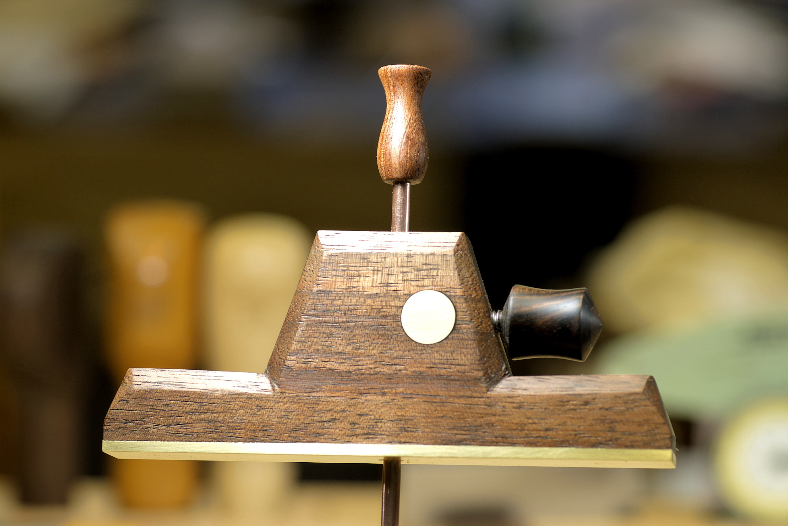
Here’s what the final gauge looks like. This is the first one I made, I am documenting building the second one. I’ll be building this tool with hand tools only.
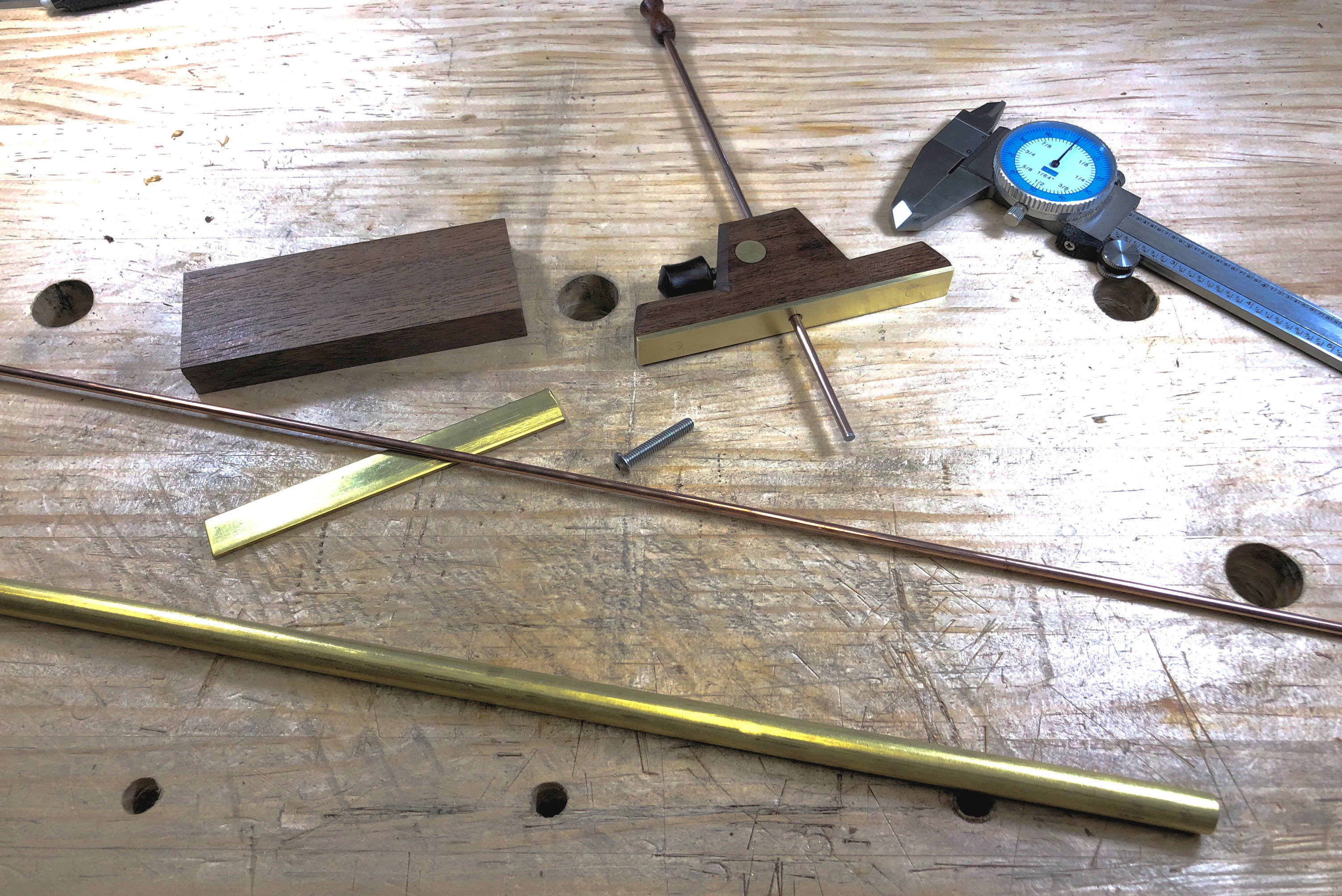
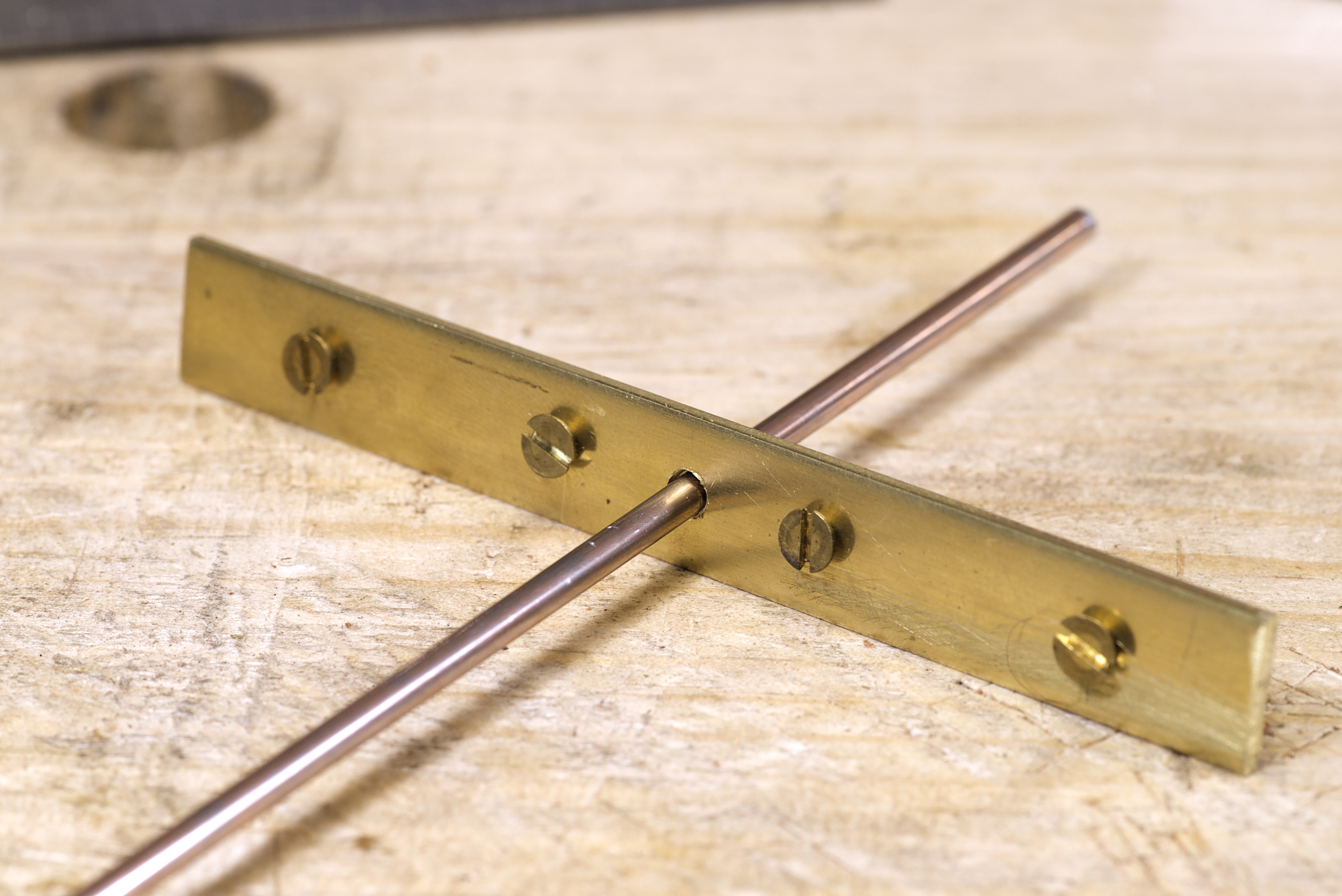
Here are the parts for the new gauge with the first gauge. The body is quarter-sawn walnut with brass and steel parts.
The 1/2" brass is marked up with the location of the center hole and the holes for the brass screws. A punch was used to make an indentation for the drill bit to follow.
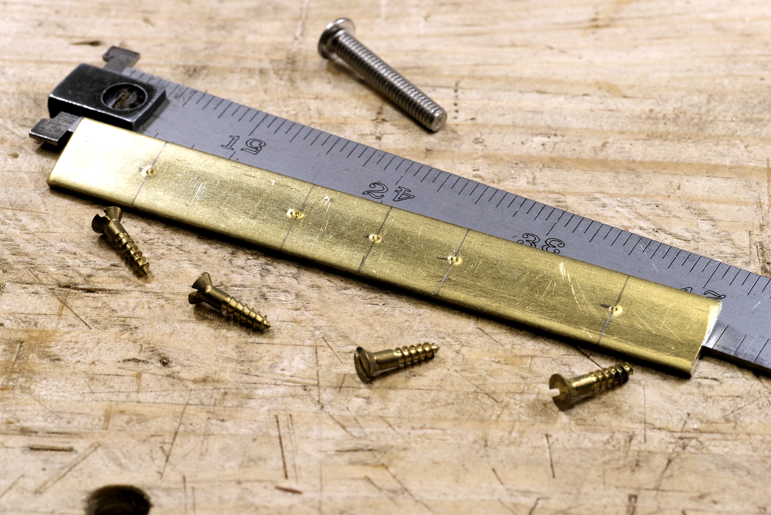
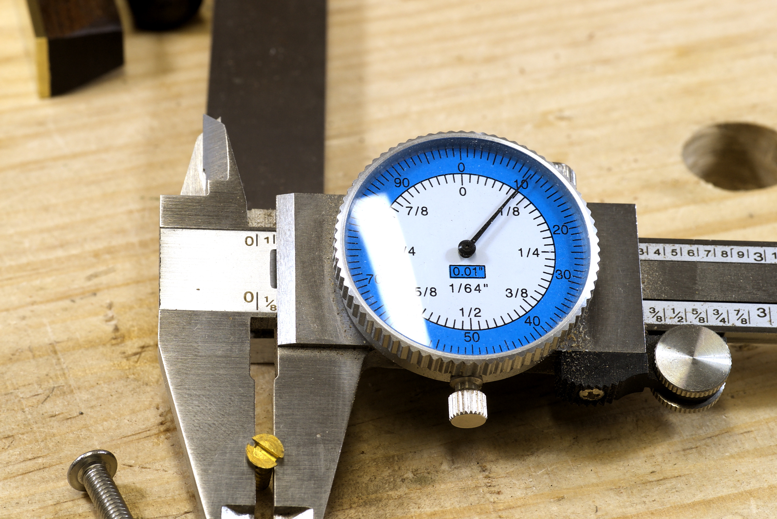
The brass screws have a shaft that is 1/64" smaller than 1/8". I’ll use a 1/8" drill bit for those holes.
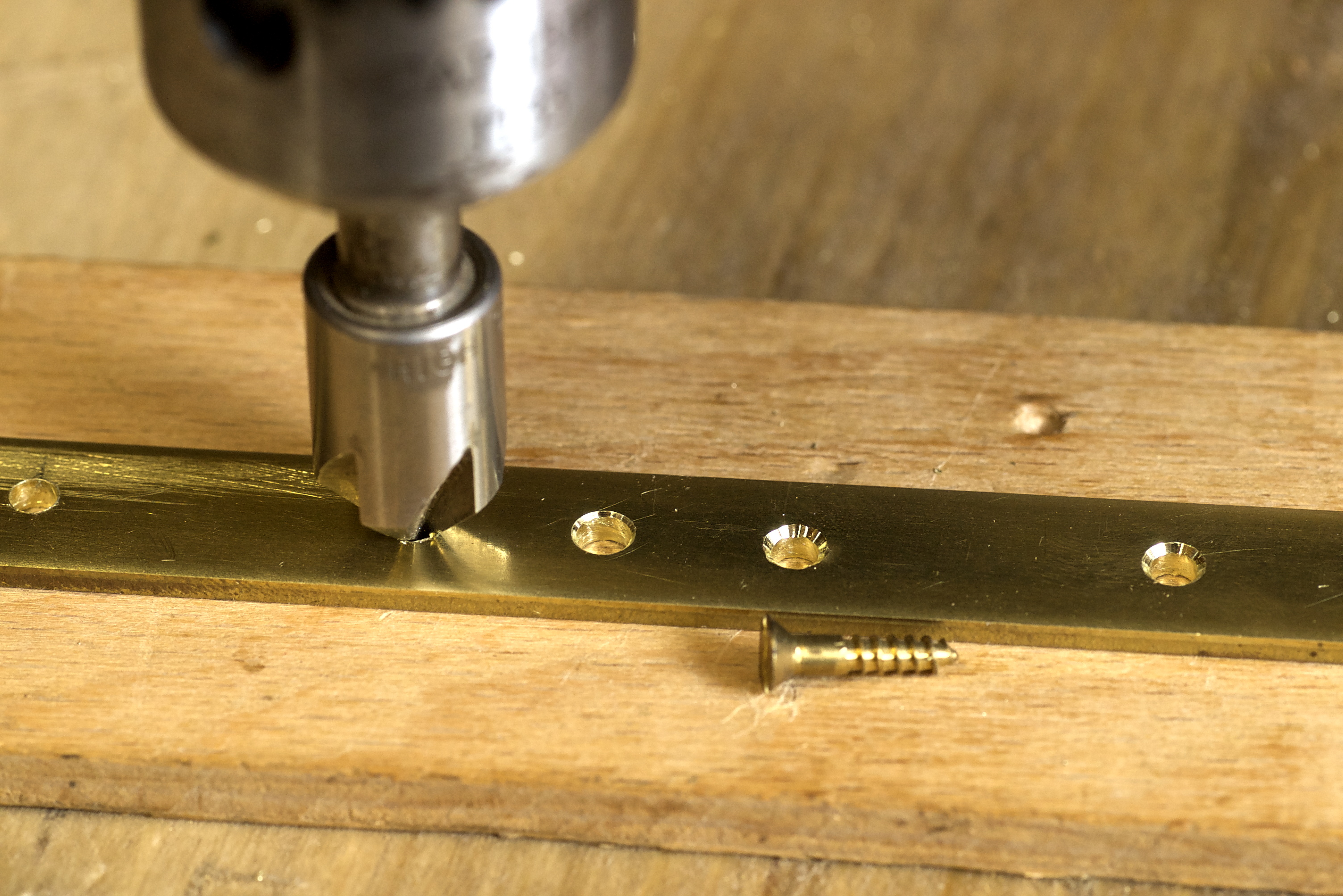
The 1/8" holes are being drilled. This looks like it’s being done with a drill press, and it is, sort of.

This is the drill press being used. It’s a post drill made around 1910 for blacksmiths. I restored it and use it heavily. It can be cranked at very low speeds which provides fine control.

The depth rod is 1/8" in diameter so I used a 9/64" drill bit for the center hole. All the holes are drilled.
Next the holes for the screws are countersunk just to the bottom of the slot of the screw. The old post drill really shines here and can do very precise work.
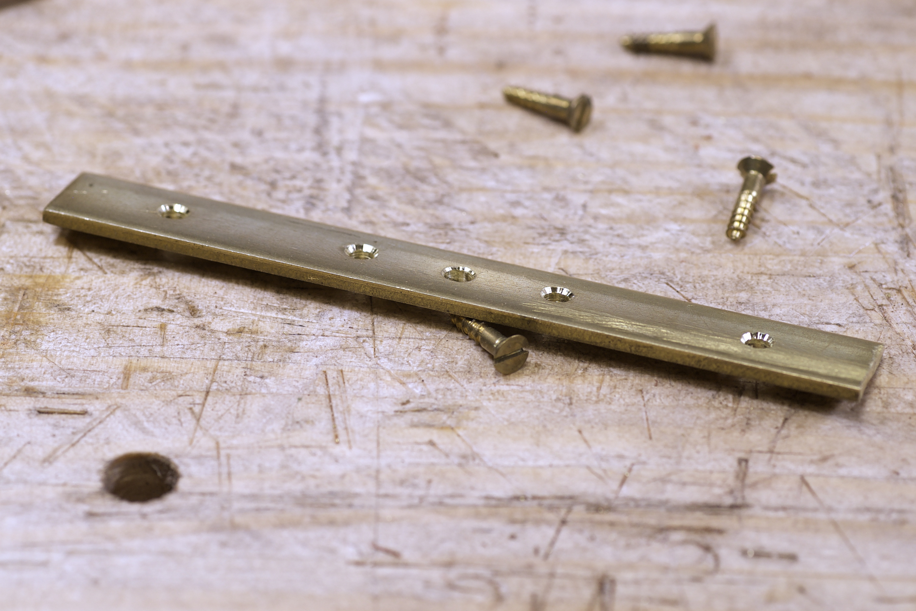
Here’s the brass sole of the depth gauge with its holes drilled and countersunk.

The brass sole is attached to the walnut blank with the brass screws. The screws are tightened down with the top of the head still proud of the sole.
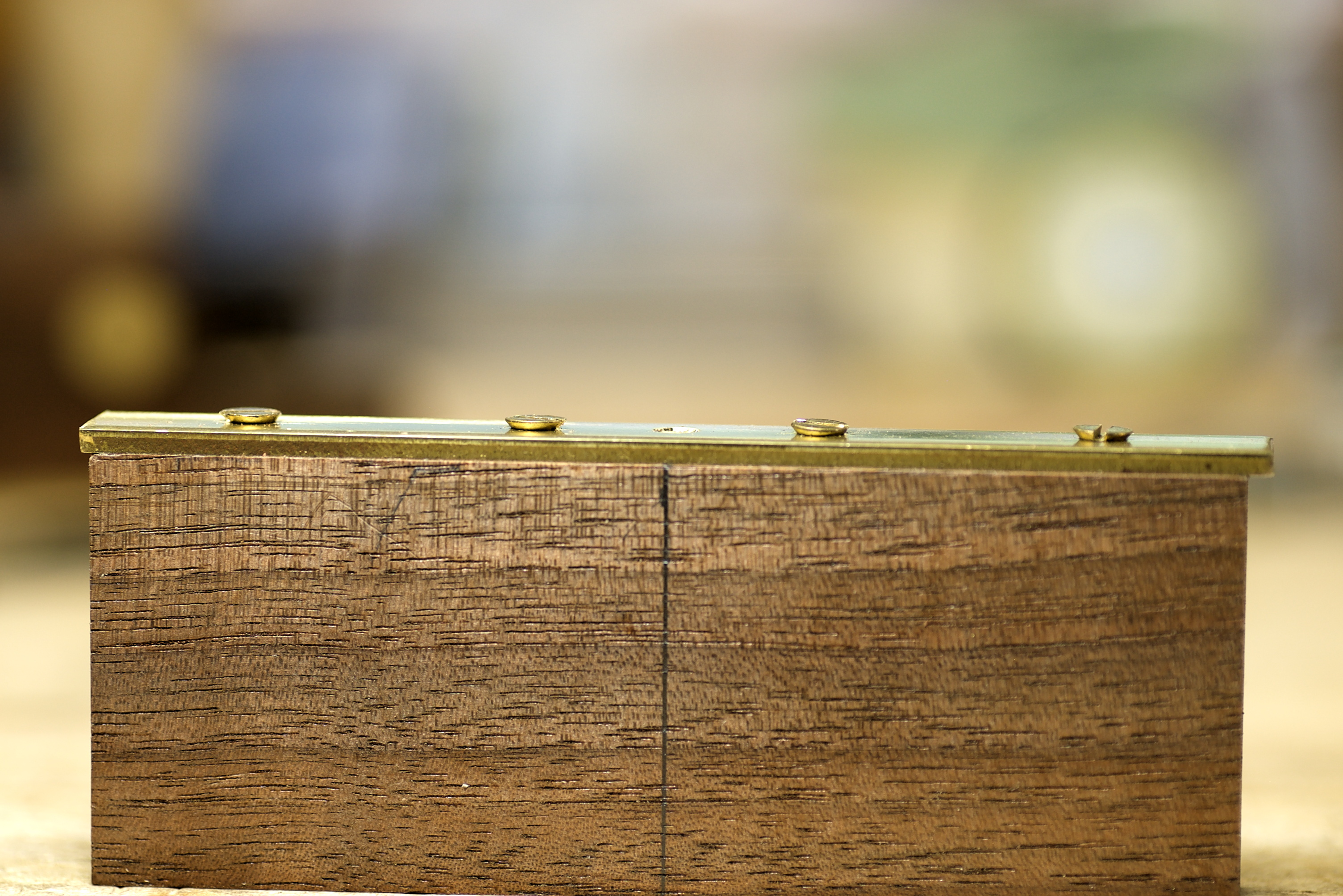
That’s part one to keep the posts smaller.
-Eric
